
No products found
Recent searches
Clear all
Bestsellers
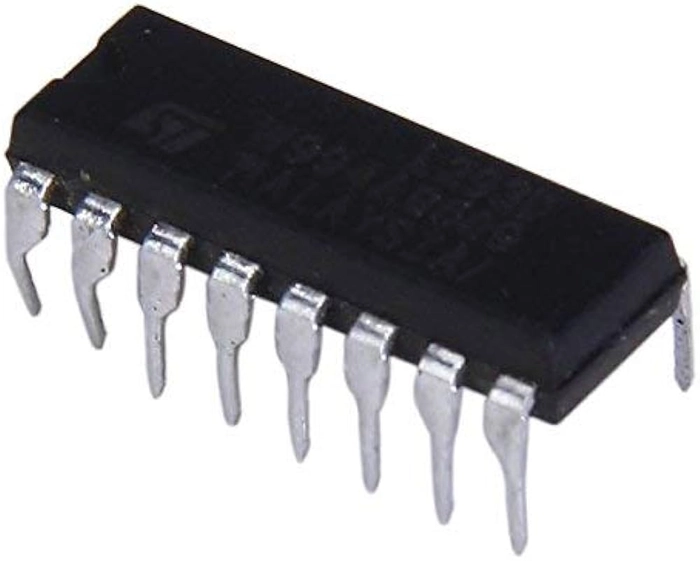
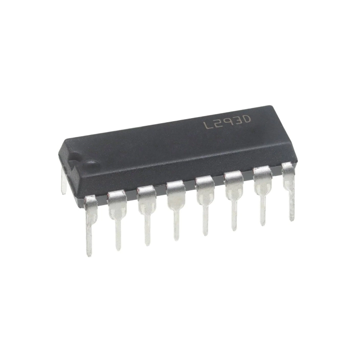
L293D PowerDIP-16 Stepper Motor Controller/ Driver
Per piece


Quick Overview
Product Description
L293D PowerDIP-16 Stepper Motor Controller/ Driver is a dual H-bridge motor driver integrated circuit (IC). Motor drivers act as current amplifiers since they take a low-current control signal and provide a higher-current signal. This higher current signal is used to drive the motors.
The Device is a monolithic integrated high voltage, high current four channel driver designed to accept standard DTL or TTL logic levels and drive inductive loads (such as relays solenoids, DC and stepping motors) and switching power transistors. To simplify use as two bridges each pair of channels is equipped with an enable input. A separate supply input is provided for the logic, allowing operation at a lower voltage and internal clamp diodes are included.
It is suitable for use in switching applications at frequencies up to 5 kHz. The L293D is assembled in a 16 lead plastic package which has 4 centre pins connected together and used for heatsinking The L293DD is assembled in a 20 lead surface mount which has 8 centre pins connected together and used for heatsinking.
L293D contains two inbuilt H-bridge driver circuits. In its common mode of operation, two DC motors can be driven simultaneously, both in forward and reverse direction. The motor operations of two motors can be controlled by input logic at pins 2 & 7 and 10 & 15. Input logic 00 or 11 will stop the corresponding motor. Logic 01 and 10 will rotate it in clockwise and anticlockwise directions, respectively. Enable pins 1 and 9 (corresponding to the two motors) must be high for motors to start operating.